Modbus Network Display
MND
Powerful Display In The Palm Of Your Hand
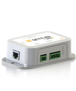
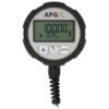
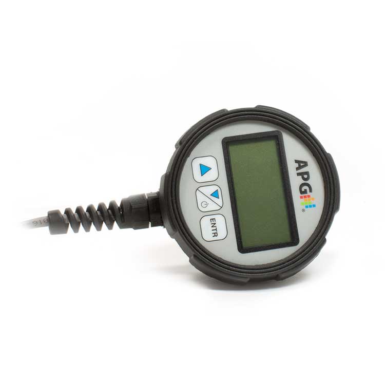
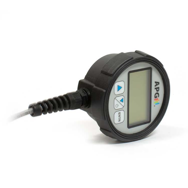
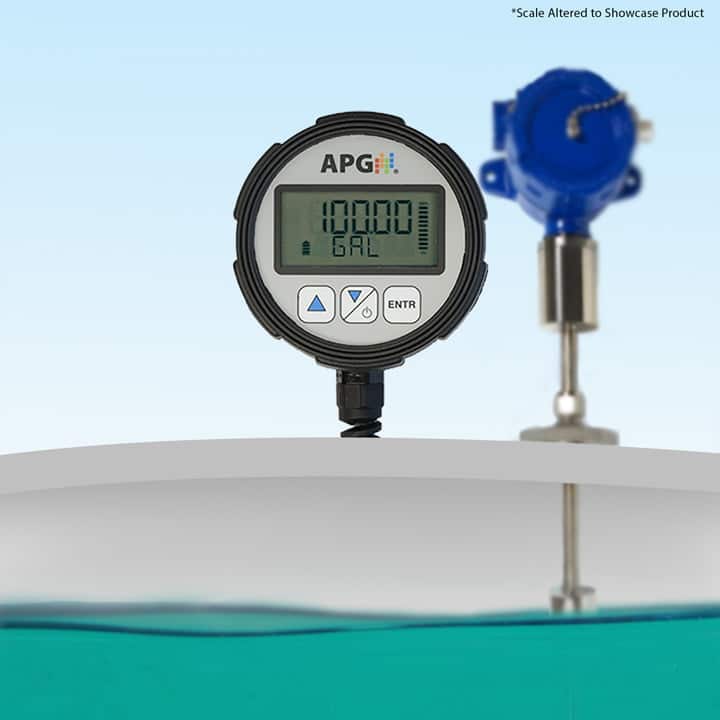
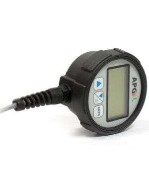
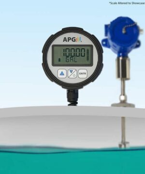
The Modbus Network Display (MND) offers versatile and powerful display capabilities for up to 10 sensors on any Modbus network, functioning as a client, server, or power source. This Modbus RTU display allows for easy monitoring of readings such as volume, level, distance, and pressure. Not only does it display sensor data, but it also provides functionality to adjust sensor settings via the Modbus registry and can even power sensors with its battery options.
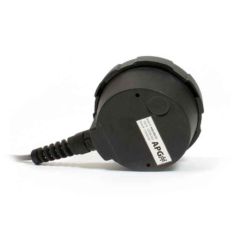
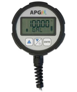
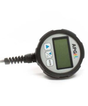
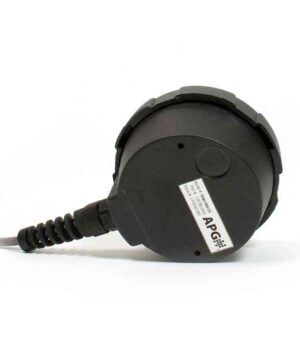
The MND is designed for simple operation with three buttons for navigation, data input, and option selection. Its local and remote applications support a variety of needs, whether for remote Internet-connected sensors or a purely local setup. Available in cast-aluminum or injected-mold plastic housing, the MND ensures robust performance and environmental protection with IP67 or IP68 ratings.
Ideal for various industrial environments, this Modbus display supports RS-485 communication, offering baud rates of 2400, 9600, 19200, and 38400, making it compatible with a wide range of systems.
- Multi-Parameter Display: Displays readings for volume, level, distance, and pressure
- Seamless Integration: Modbus RTU compatibility (RS-485 communication)
- Flexible Power Options: Battery-powered or external power options
- User-Friendly Operation: Simple navigation with 3-button interface
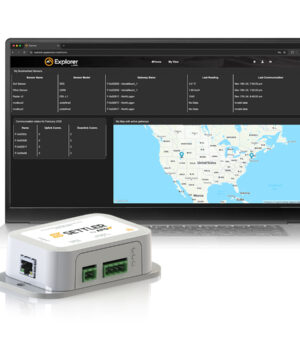
- Versatile Deployment: Local and remote applications support
- Rugged Durability: Available in IP67 or IP68 rated housing for durability
- Customizable Outputs: Multiple relay and output options